The cheapest of the ESP8266 boards is a pretty annoying board to deal with. But its small form factor and its tremendous capabilities make it absolutely ideal for IoT projects. After failing initially a few times to get it working, I resorted to using a NodeMCU version of the board as it had an inbuilt USB connection. But soon, that footprint and cost pushed me to find a reliable way to program the ESP 01. I faced a lot of pitfalls and decided to document my effort so that it may in future help another poor soul.
Identify the board
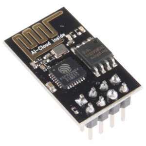
Firstly how do you identify an ESP 01 board. If your board looks like the one below, there is a good chance that you are on the right track.
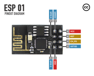
The pinout for the board is as follows:
Building the programmer
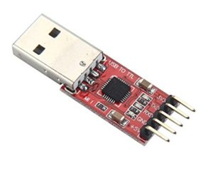
In my case, I happened to have a CP2102 based USB to Serial adapter like the one shown in the picture below. Any similar USB to serial adapter should also work for the same. This form of programmer has two flaws:
- It does not supply the required 3.3V power to the ESP board (either due to lack of a 3.3V source or due to that port not being able to source enough current)
- There is no provision to boot the ESP in Flash mode and Regular boot mode
In either case we will move on to build an adapter that will interface between the USB to Serial board and the ESP 01 Board.
We will wire up a board according to the following schematic
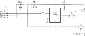
The board primarily does 4 things:
- Swap the Transmit and Receive (TX/RX) to the ESP
- Supply 3.3V power to the ESP using a Linear regulator
- Provide push buttons to independently ground the Flash (GPIO0) pin and the Reset pin
- Enable the chip by pulling up the pin.
Ensure that the ESP 01 board is not permanently wired in so that the board can be reused to program other ESP 01 chips.
Programming
Now that we have all 3 components ready, namely the USB to Serial adapter, ESP 01 and the programmer board that we made, we can start programming the ESP 01.
We will first need to ensure that we have the CP2102 drivers installed in our computer and our IDE ready to program the code. I am using the Arduino IDE to program the ESP board. Once we have that setup, we can begin to program as follows.
- Connect the ESP board to the programmer and the programmer to the computer.
- Select the USB to UART port in the compiler options (
Tools>Portfor Arduino) (for CP2102 the port should be something like/dev/cu.SLAB_USBtoUART) - Set the ESP into flashing mode by holding down the FLASH button (GPIO0) while resetting the board (pushing and releasing the RESET button) and then releasing it.
- Click the Upload button on the IDE
If all goes well, the Upload should begin and the light on the ESP should begin to blink continuously.
Conclusion
The ESP 01 board has a little bit of a learning curve to it, and the unwieldiness of the board and the difficulty in programming it only compound the issue. But once you overcome these hurdles, it has quite a lot to offer. So to those that look at this article or other such similar ones and back away from it, I advise you not to give up. It is well worth the effort and I myself am now throughly enjoying what Ive built with it.